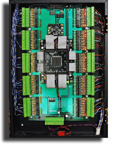
Digital input/output - human/computer interface controller
Spartan 3 FPGA based Digital IO controller accepts
instructions from a computer as well as human interface
contact switches. Momentary closure of optically isolated contact switches
provides a passive input that controls corresponding outputs(devices). Host computers can read and toggle
devices based on program logic. In this manor control of devices will
continue in the event of a software/firmware crash.
Built
in fail safe feature allows the input switch actions to continue controlling
the outputs in the event that the host computers program stops running.
Input signal conditioning is achieved by using a unique digital switch de-bouncing circuit
combined with gated and-or inputs.
Outputs can be configured for flip/flop, latch or follow input. Multiple boards can be daisy chained together to provide
1,200 high current high speed Digital IO control lines.
System bus has its own isolated ground and all interface lines are optically isolated and protected from ESD.
-
- 60 switch de-bouncing optically isolated inputs
- 60 high current TTL
outputs (80 ma Darlington driver on each output)
- Phoenix style quick
connect screw terminals
- Up to 10 boards can be
daisy changed for a total of 1,200 control points
- Riser backbone bus max
length 150 ft
- Individual signal lines max distance 3000 ft per line
- Field
programmable to perform:
- Mode 1: output follows input (switch de-bounced signal)
- Mode 2:
output latches on input pulse (reset by program logic)
- Mode 3 output toggles when input
state is pulsed (switch de-bounced signal)
- Quick connect screw type terminal strips
- 5 VDC operation voltage
-
-11c to 90c operational temp
- 20 ns response on all channels
- Connects to 8255 PIA compatible IO bus
(PIA DIO adapter card on host)
-
Selectable bonded or isolated ground plane
- Output indicator LEDs
- Firmware
upgradeable
- .net API with code in C#
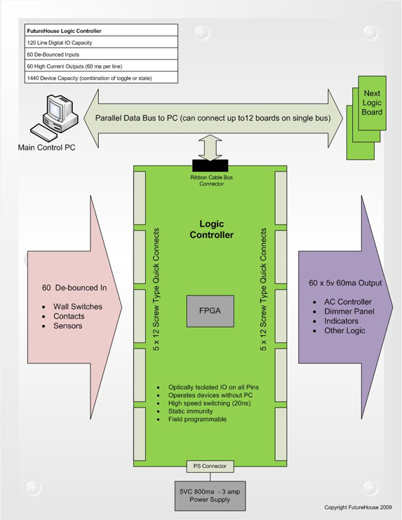
Diagram:
Configured with PC on parallel GPIO Bus. Boards can also be connected via
Ethernet using
Raspberry Pi controllers connected to board bus connector.
|